
I've been making some SMT stencils using a Silhouette Cameo craft cutter (vinyl cutter). It's great for fast turnaround time and low materials cost, though the quality is not as high as a laser-cut stainless-steel stencil. Still, they're useful down to 0.5 mm pitch and 0201, and possibly a little better, and that's good enough for many applications.
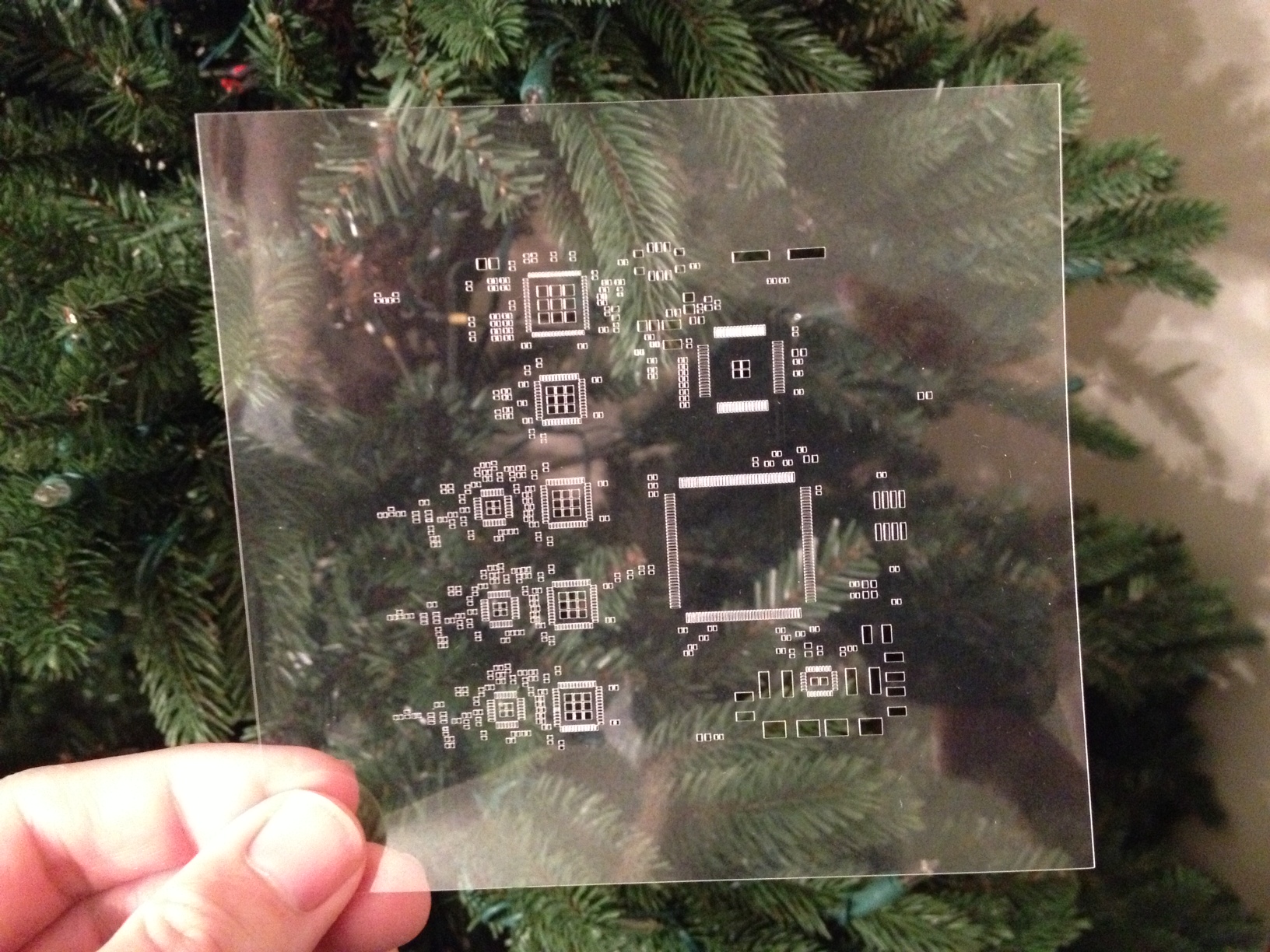
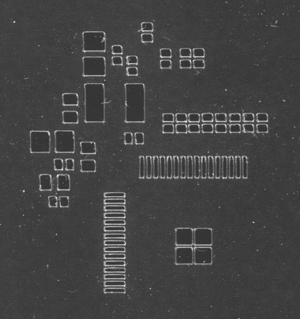
Here's a stencil cut by the Cameo. The partial QFP footprint is 0.5 mm pitch and the smallest discretes are 0402.
gerber2graphtec examples/test_0.5mm_0402.gbr >/dev/usb/lp0
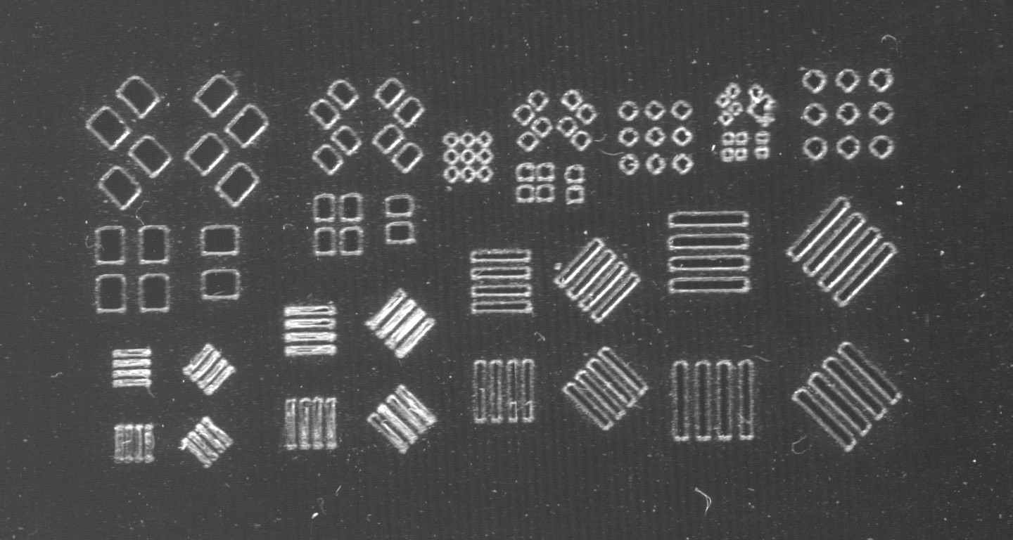
And a test coupon with QFP pitch from 0.65 mm to 0.3 mm, discretes from 0603 to 01005, and BGA pitch from 1.0 mm to 0.5 mm:
Background
The web page that got me looking at craft cutters was this one:
http://www.idleloop.com/robotics/cutter/index.php#stencil
These results are very nice, but on the software side I wanted something that fits into a normal PCB workflow with no hassle, by working directly from the solderpaste Gerber file as exported by a PCB CAM tool.
In addition, I wanted the best quality possible. Using the cutter in its default mode rounds off corners considerably due to the drag-knife mechanics, so instead I dice all features into individual line segments and draw them separately in multiple passes. Also, machine backlash is an issue, so the software works around that, at the expense of speed.
Fortunately, the low-level protocol for these machines has been documented, and the rest is mere geometry conversion that's considerably helped by existing tools like gerbv and pstoedit. The software can be found here:
https://github.com/pmonta/gerber2graphtec
Also included are some example Gerber files. A test coupon with QFP/QFN and BGA pitches from 0.65 mm down to 0.3 mm and two-pad footprints from 0603 to 01005 is included, as well as a few larger examples.
The generated files run well on my Silhouette Cameo and probably on other similar Graphtec cutters as well.
Materials
Polyester film is a natural choice. It's inexpensive, dimensionally stable, and very available in the form of laser-printer or copier transparency sheets. Thickness of these sheets is usually around 4 mils, close to the IPC-recommended values for fine-pitch work. Other thicknesses can be obtained easily enough from sources like McMaster-Carr.
I'm using Highland 901 sheets (a 3M brand apparently) together with full-sheet Avery labels, number 5353, as an adhesive backing sheet. The adhesive is a little too aggressive and can be difficult to remove cleanly once the stencil is finished. One can use Goo-Gone or similar citrus-oil cleaner to remove all the adhesive, and this results in a squeaky-clean stencil, but it takes a few minutes of extra time. Perhaps it would be better to use the cutter's cutting mat, though cleaning off the small plastic chads is a bother too. Another option might be to use a separate full-sheet double-sided low-tack adhesive to laminate a plastic sheet to a plain paper backing.
Calibration
Two aspects of the machine should be calibrated for best performance: cutting force and the spatial coordinate system.
For force, the software includes an example script that produces 30 small squares, each cut with a different force. Just have a look at the result to see which force settings result in good performance with your material stackup (mylar plus adhesive backing): first, a reasonable initial cut, to score the material, and second, a final pass that aims to cleanly separate the unwanted material from the stencil background.
For axis calibration, a script is provided to cut a calibration artifact. Measure the distance between marks along each direction (x, y, 45 degrees, and -45 degrees), then calculate a matrix to take out the distortion. (Rub in a bit of felt-tip-pen ink to make the marks more visible when comparing against a good ruler. The provided script produces a 17-step vernier against a 1/16-inch ruler; modify this for 11 steps against a 1 mm ruler if you're using a metric ruler.) My machine is pretty reasonable in x, has a rather large 0.6% error in y, and has a skew of about 1 milliradian. After compensation I think the error is down to less than 0.1%. Even this is uncomfortably high: it is still a 50-micron positioning error across half the dimension of a 100 mm board.
Platform notes
So far I've run this only under Linux (Fedora), which provides a device node at /dev/usb/lp0 when the device is plugged in. Other platforms may need different device-driver arrangments. One can always send the output of gerber2graphtec to a file and deal with getting it to the cutter separately. Fortunately no feedback from the cutter seems to be necessary.
Application notes
Perhaps these stencils are best suited to prototyping that needs very fast turnaround. For example, it's sometimes convenient to populate and test only parts of a board, and for this separate stencils can be cut for each region.
I plan to evaluate at some point this source of laser-cut Kapton stencils:
http://ohararp.com/Stencils.html
as well as the various lower-end laser-cut stainless vendors.