Is it possible to make an op-amp out of nothing but 555 chips and passive components? Not a terribly practical question, given the existence of very inexpensive and capable op-amps covering every corner of op-amp performance space; but it has some aesthetic appeal. If you find yourself on a desert island with nothing but a pile of 555s and a need for an op-amp, by all means read on.
The 555 has two comparators, but offers direct access to neither. The "trigger" comparator could conceivably work with feedback from the control pin, but the existence of a 2:1 resistive divider in the feedback path is very awkward. And while the "threshold" comparator sees both the input pin and the control pin directly, unfortunately its output can't flow through the digital portion of the 555: the threshold comparator can only reset the RS latch, not set it.
Even if we could use the threshold or trigger comparators directly, they have the disadvantage that one of their inputs is tied to a resistive bias network, resulting in a very low input impedance on that input (in the neighborhood of 30k ohm for the CMOS flavors of the 555; 3k ohm for bipolar). Potentially tolerable for something like a unity-gain buffer, where a low-impedance output drives the input pin, but not good for a general-purpose op-amp.
So instead we can adopt the following approach:
The schematic below shows one implementation. I used the TS555 from ST Microelectronics; it is a CMOS 555 with improved specs over the bipolar original.

First, a conventional astable oscillator generates a sawtooth waveform ranging between 1/3 Vcc and 2/3 Vcc. This is fed to the control inputs of two additional 555 chips serving as analog comparators; their outputs encode the op-amp input voltages as PWM waveforms. The digital gates (implemented with 555 chips, of course, as shown at the bottom of the schematic) compare the edges of the PWM waveforms, generating pulses if waveform A is ahead of waveform B or vice-versa. These pulses are integrated with a capacitor, using diodes to isolate the two totem-pole outputs (I suppose one could dispense with the lower diode and use the open-drain 555 pin instead). Ten 555 chips are used in all.
This is all quite similar to a charge-pump PLL. In fact I built the circuit first without the inverter pairs and wound up with some flaky behavior: hysteresis, distorted waveforms, etc. This is because at equilibrium the edges are very close together and the gates cannot generate pulses narrow enough to represent the tiny phase difference. The solution is the same one the PLL chips use: anti-backlash delays. The inverter pairs introduce enough delay so that at equilibrium, pulses are generated in both plus and minus arms, which cancel once they hit the integrating capacitor. And now small PWM edge movements result in linear net charge to the capacitor.
Speaking of PLLs, another possible op-amp implementation would use voltage-to-frequency converters at the inputs, then compare the frequencies with a sequential ("type-IV") phase-frequency detector, again implemented with 555 chips. But besides being more complicated, one might worry about injection locking. I ended up not trying it.
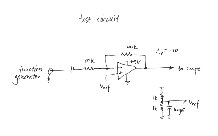
The test circuit is a simple inverting gain-of-10 amplifier:
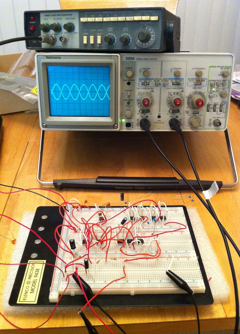
Here is the breadboarded system:
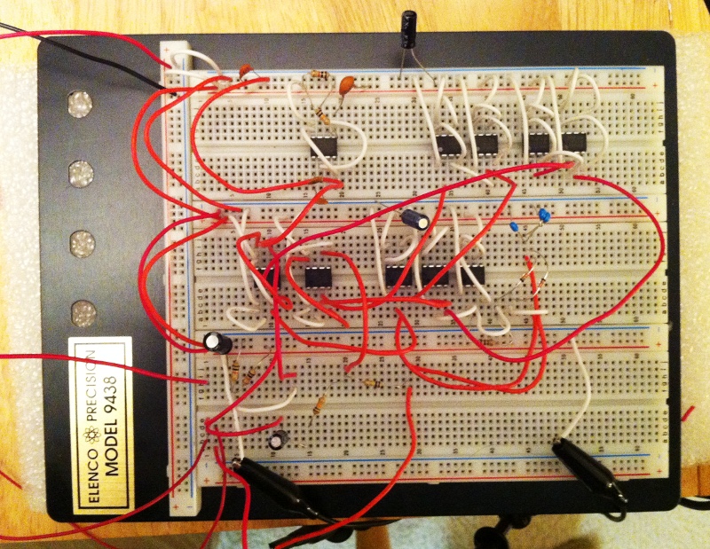
and a closeup of the breadboard:
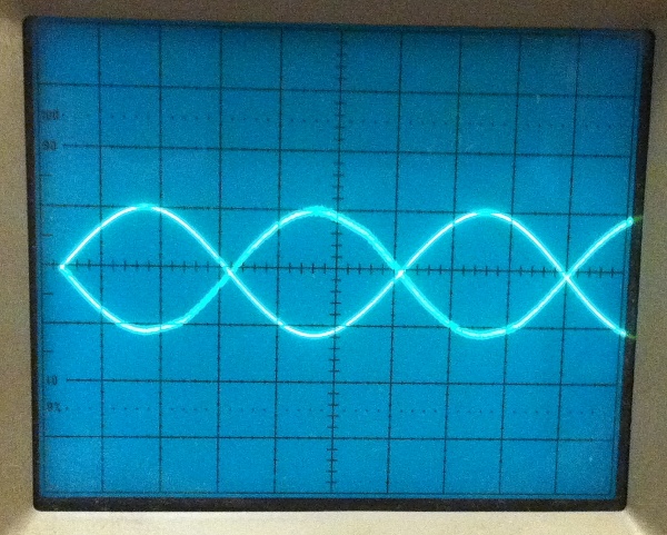
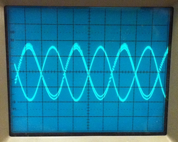
This scope trace shows an input of 100 mV peak and an output of about 1 V peak:
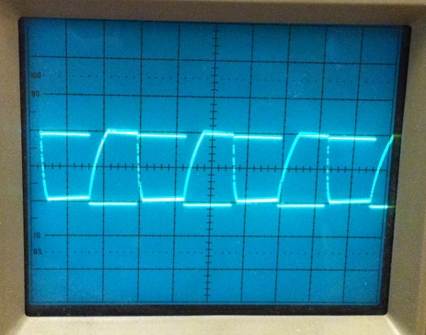
Same thing but with square waves; note the asymmetry in the large-signal response between rising and falling edges:
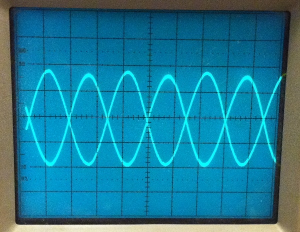
Smaller amplitude signal, 30 mV in, 300 mV out. Note the "fuzz" on the output waveform; these are the high-frequency steps on the output from the error pulses. Low-pass filtering the output attenuates this fuzz and results in a clean waveform:
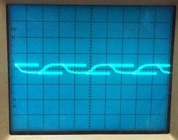
Finally, here is a low-amplitude square wave as input (about 6 mV peak), still with the low-pass filter on the output. The output is more symmetrical than in the large-signal example. Horizontal scale is 200 microseconds per division.
Despite the low gain-bandwidth product (about 10 kHz), this op-amp might be usable for some low-frequency applications, such as general-purpose amplification, sine-wave oscillators (e.g. Wien bridge or RC phase-shift), active filtering, or even analog computation.
Possible enhancements:
My other contest entry is here:
Digital logic using 555 chips